Leave Your Message
  • sns02
  • linkedin (2)
  • sns041
  • whatsapp (2)

10 Tips to Choose the Right Piezo Ceramic Disc?

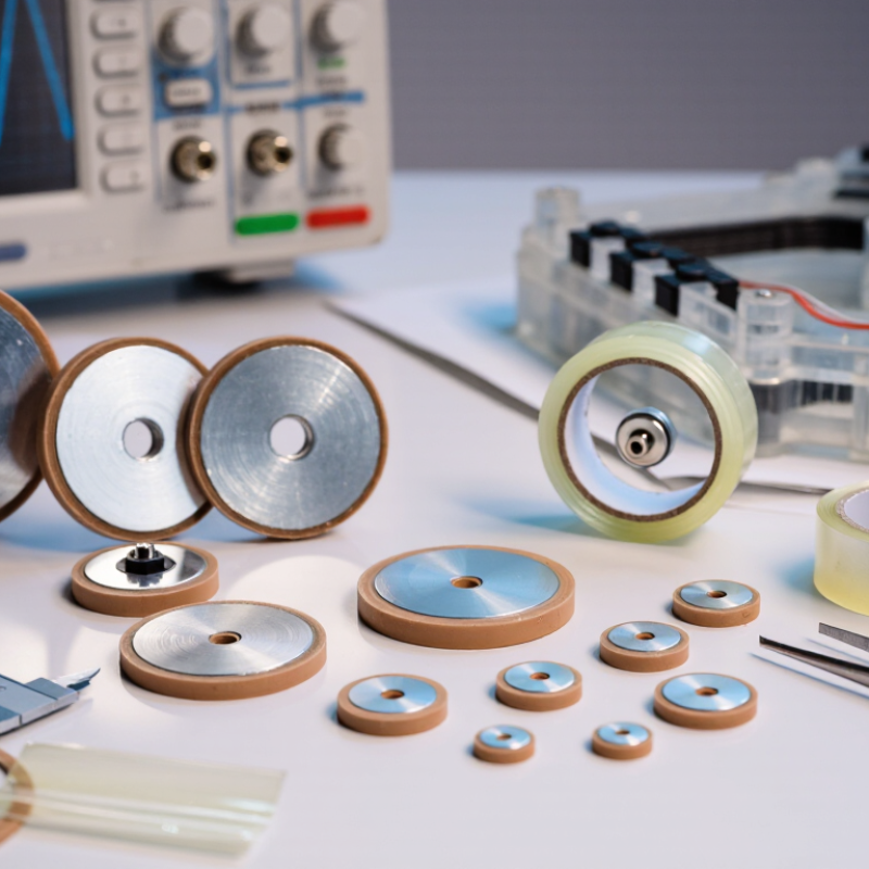
Choosing the right Piezo Ceramic Disc can determine whether a device produces a clear signal or a disappointing buzz. In practical projects, small differences in diameter, thickness, and electrode design can change sound pressure, sensitivity, and operating stability. A disc that looks suitable on a supplier’s page may behave differently after bonding, wiring, or enclosure installation.

This guide examines ten useful selection points for engineers, product developers, and careful buyers. It considers operating frequency, capacitance, resonance, voltage range, acoustic output, and environmental conditions. Material composition also matters. PZT ceramics often provide strong electromechanical performance, while other formulations may suit lower-power or temperature-sensitive applications. Check the datasheet carefully. Marketing descriptions are not enough.

Physical details deserve equal attention. A 27-millimeter disc may fit the circuit but fail inside a crowded plastic housing. Adhesive thickness can reduce vibration. Uneven soldering may create stress around the electrode. These problems are easy to overlook. They should not be.

Reliable selection also requires evidence from testing. Compare samples at the intended voltage, frequency, and mounting condition. Record sound output, current, temperature rise, and frequency drift. Ask suppliers for tolerance data, aging information, and quality-control records. One weakness in this approach is that laboratory results may not match field performance. Real products face humidity, repeated vibration, and careless assembly. That is why a suitable Piezo Ceramic Disc should be judged by both specifications and application trials, not appearance alone.
10 Tips to Choose the Right Piezo Ceramic Disc?

Understanding Piezo Ceramic Disc Types and Operating Principles

Choosing the right piezo ceramic disc starts with its operating principle. When voltage crosses its electrodes, the ceramic expands or contracts. Mechanical stress reverses this process and produces voltage. This is the piezoelectric effect.

Disc structures behave differently. A single-layer disc suits simple buzzers and contact sensors. A bimorph disc bends more noticeably, making it useful for vibration and low-frequency movement. Multilayer elements provide larger displacement at lower voltage. Hard ceramic materials handle stronger drive conditions, while softer materials usually offer greater sensitivity. Check the piezoelectric coefficients, especially d31 and d33. They reveal how the disc deforms.

Resonance matters greatly. A disc may sound weak outside its designed frequency. Measure the resonant frequency with the final housing, not only on the workbench. The enclosure changes stiffness. It also changes sound output. Capacitance affects driver selection and current demand. Confirm the allowable voltage, temperature range, electrode layout, and bonding method. A thin disc may respond quickly but crack during assembly. I once trusted a clean frequency graph too much. The mounted part behaved differently. That mistake taught me to test samples under real pressure, temperature, and adhesive conditions. Datasheets help, but they do not replace measurement. Check batch variation as well. Small differences can become obvious in sensitive instruments.

Matching Disc Size, Frequency, and Resonance Requirements

10 Tips to Choose the Right Piezo Ceramic Disc?

Choosing a piezo ceramic disc starts with the mechanical task, not the catalog photograph.

Measure the available surface, enclosure depth, and mounting area first. A larger diameter can produce stronger acoustic output, but it also needs more space. Thickness affects stiffness, capacitance, and operating frequency. For a compact alarm, a 20 mm disc may be suitable. A sensing device may need a smaller, more stable element.

Match the disc’s resonant frequency with the working frequency of your circuit.

Check whether the specification describes free-air resonance or mounted resonance. These values can differ significantly. Adhesive, screws, protective films, and housing pressure all change vibration behavior. In bench testing, I have seen a disc shift several hundred hertz after installation. That detail is easy to miss. Select a frequency tolerance that fits the application, rather than choosing the closest nominal value.

Drive voltage and impedance also deserve attention.

A disc may resonate correctly but overload a small driver. Review capacitance, current demand, and continuous operating limits before testing. Sweep the frequency slowly around the expected peak, then measure sound pressure or sensor output. Do not rely only on a hand calculation. Temperature and production variation can affect the result. My early selections sometimes favored maximum output, but long-term stability mattered more. A quieter disc can be the better engineering choice.

Evaluating Voltage, Sensitivity, and Electrical Performance

10 Tips to Choose the Right Piezo Ceramic Disc?

Evaluating Voltage, Sensitivity, and Electrical Performance

Voltage ratings deserve careful attention. A disc driven above its specified level may crack, heat, or lose polarization. IEEE Std 176-1987 recommends measuring piezoelectric constants under defined electrical and mechanical conditions. This matters because “sensitivity” changes with frequency, mounting pressure, and load resistance. A laboratory value is not always a field value.

Check the operating frequency first. Many acoustic discs perform strongly near resonance, but resonance can shift after bonding. A practical test should sweep frequency across the expected range, then record sound pressure or output voltage. Recent technical reviews in Sensors report common PZT d33 values around 200–600 pC/N, yet this coefficient alone cannot predict disc sensitivity. The electrode area, thickness, damping, and circuit design also matter. Small details matter.

Electrical performance needs more than capacitance. Measure capacitance at the intended test frequency, leakage current, impedance, and phase angle. A typical disc may show capacitance from several nanofarads to hundreds of nanofarads, depending on geometry and ceramic formulation. Use a high-impedance meter when checking open-circuit voltage. Otherwise, the instrument itself can suppress the reading.

I would also test the disc after bonding, not only before assembly. Adhesive stiffness can reduce vibration. That mistake is common. For repeatable selection, log drive voltage, frequency, temperature, mounting method, and measured output. IEC and IEEE methods improve comparability, but they do not replace application testing. Real fixtures often expose weaknesses that clean laboratory measurements hide.

10 Tips to Choose the Right Piezo Ceramic Disc? - Evaluating Voltage, Sensitivity, and Electrical Performance

Tip Evaluation Factor What to Check Typical Reference Data Selection Guidance Recommended Verification Method
1 Application Frequency Confirm the operating frequency and whether the disc will be driven near its mechanical resonance. Approximately 1–10 kHz for many audible piezo discs; resonance depends strongly on diameter, thickness, electrode design, and mounting. Choose a disc whose resonant frequency is close to the target frequency for maximum sound output. Select a non-resonant design when a wider frequency response is more important. Measure impedance or admittance with an LCR meter or impedance analyzer while sweeping across the intended frequency range.
2 Drive Voltage Check the continuous and peak voltage limits, waveform, duty cycle, and driver output capability. Common small-disc drive levels: 5–30 VRMS; some specialized parts require substantially higher voltage. Always follow the component specification. Use the lowest voltage that meets the required acoustic or displacement output. Excessive voltage can cause cracking, depolarization, overheating, or premature failure. Measure the actual voltage directly across the disc with a suitable oscilloscope probe and verify both RMS and peak-to-peak values.
3 Capacitance and Reactive Current Evaluate capacitance at the intended test frequency and calculate the current required by the driver. Approximately 5–50 nF is common for small metal-backed piezo discs, although size and ceramic thickness can produce wider values. For a capacitive load, estimate current using IRMS = 2πfCVRMS. Ensure the driver can supply the reactive current without excessive voltage distortion. Measure capacitance at 1 kHz and, where possible, again at the actual operating frequency and voltage.
4 Acoustic Sensitivity Compare sound-pressure level, test distance, drive voltage, and test frequency rather than relying on sensitivity alone. Roughly 80–100 dB SPL at 10 cm is possible for resonant buzzer-type assemblies under specified test conditions. Select the disc with the required SPL at the target frequency. A higher sensitivity rating is meaningful only when the measurement conditions are comparable. Measure SPL in a controlled acoustic environment using the same voltage, frequency, distance, enclosure, and mounting method.
5 Piezoelectric Sensitivity For sensor applications, review charge sensitivity, voltage sensitivity, or the relevant piezoelectric coefficient. Common PZT materials may have g33 values around 10–30 mV·m/N; actual values vary with composition and polarization. Use charge-mode materials and a high-input-impedance amplifier for low-frequency sensing. For actuator use, prioritize displacement, force, and required drive voltage. Apply a known mechanical force or stress and measure the generated charge or open-circuit voltage with a calibrated setup.
6 Mechanical Displacement and Force Determine whether the disc must create audible vibration, detect small deformation, or produce useful mechanical motion. Free displacement is generally small, often in the micrometer or sub-micrometer range, while blocked force depends on diameter, thickness, voltage, and mounting. Use larger or thinner discs for greater displacement when appropriate. Avoid excessive clamping, which can reduce output and introduce mechanical stress. Measure displacement with a laser displacement sensor or a microscope-based optical method at the intended frequency and voltage.
7 Electrical Insulation and Leakage Check insulation resistance between electrodes and any conductive metal substrate, especially in humid or high-voltage environments. A practical screening value is often greater than 100 MΩ at 100 V DC, subject to the application specification. Choose higher insulation resistance for battery-powered sensors, high-impedance amplifiers, and high-voltage drive circuits. Protect exposed electrodes from moisture and contamination. Use an insulation-resistance meter after conditioning the part at the intended temperature and humidity.
8 Dielectric and Voltage Margin Review dielectric strength, maximum electric field, polarity, and risk of depolarization during operation. Typical PZT ceramics have dielectric strengths in the order of 1–3 kV/mm, but practical operating limits are lower and depend on defects, edges, and electrode quality. Maintain a safety margin below the rated field. Avoid DC bias unless the disc is specifically designed for it, because prolonged high electric fields can reduce polarization. Perform a controlled hipot or withstand-voltage test only within the limits of the applicable safety standard and component specification.
9 Temperature Stability Compare the operating temperature range, Curie temperature, temperature coefficient, and polarization stability. Many hard and soft PZT formulations have Curie temperatures approximately in the 200–350°C range; continuous operation should remain well below this limit. For reliable long-term performance, select a part whose specified operating range comfortably exceeds the application temperature, including heating from self-loss. Measure capacitance, resonance, sensitivity, and leakage at the minimum and maximum expected temperatures.
10 Mechanical Construction and Tolerance Inspect disc diameter, ceramic thickness, brass or stainless-steel backing, electrode finish, lead attachment, flatness, and dimensional tolerance. Common disc diameters are approximately 10–50 mm; capacitance and resonance tolerances of ±10% to ±20% are common unless tighter control is specified. Match the mounting method to the design. Bonding, clamping, soldering temperature, and adhesive stiffness can significantly change resonance and sensitivity. Check dimensions with calibrated tools, inspect solder joints and electrodes, then repeat electrical and acoustic tests after final assembly.

Note: The values shown are general engineering reference ranges for unbranded piezoelectric ceramic discs. Actual performance depends on ceramic formulation, disc geometry, polarization, mounting, drive waveform, test frequency, temperature, and measurement conditions.

Selecting Materials, Mounting Methods, and Environmental Durability

Choosing the right piezo ceramic disc starts with the material, not the diameter. Lead-based PZT ceramics usually provide strong coupling and stable sensitivity. Lead-free compositions can reduce regulatory concerns, but their output and temperature stability may vary. The 2024 MarketsandMarkets industry report estimates the piezoelectric devices market at about USD 1.7 billion in 2023, with continued growth through 2028. That expansion increases material choices, but it does not remove the need for testing.

Mounting changes performance dramatically. A rigid clamp may improve mechanical transfer, yet excessive pressure can crack the disc or shift its resonant frequency. A thin, flexible adhesive layer often works better for vibration sensing. Keep adhesive away from the active center. In bench testing, small differences in bond thickness produced noticeable signal changes. That result is easy to overlook. Review the datasheet for capacitance, resonance, coupling factor, and maximum drive voltage before fixing the disc permanently.

Environmental durability requires more than a temperature rating. Test humidity, thermal cycling, vibration, and chemical exposure using relevant IEC 60068 methods. A sealed housing can protect the electrodes, but trapped moisture may still corrode connections. Consider the full assembly, including wires and adhesive. The U.S. Department of Energy’s 2023 materials research reporting highlights growing interest in lead-free functional ceramics, although long-term field data remains less consistent than expected. That uncertainty deserves attention. Choose the disc only after testing the mounted assembly under real operating conditions.

Comparing Suppliers, Quality Standards, and Total Product Value

Selecting the right piezo ceramic disc involves more than matching diameter and capacitance. Supplier quality matters just as much as the component’s data sheet. Ask for tolerance records, material details, lot traceability, and clearly defined resonance measurements. Reliable suppliers explain their test methods instead of sending unexplained numbers.

Request samples from several suppliers and test them under identical conditions. Measure capacitance, impedance, sensitivity, and resonance at a controlled temperature. Small changes in electrode thickness can affect performance. Check whether production follows recognized quality systems, such as ISO 9001, and whether materials meet applicable RoHS and REACH requirements. Certificates help, but they do not replace your own inspection.

Look beyond the unit price. Total product value includes yield, packaging protection, delivery consistency, technical support, and replacement risk. A low-cost disc may create expensive failures during bonding or final assembly. Review vibration results, humidity testing, and temperature cycling data when the disc will face demanding conditions. Ask how rejected parts are controlled. It matters.

I have seen a polished report hide weak process control. That deserves reflection. A practical comparison should include a sample approval record, response time, minimum order quantity, and warranty terms. Also examine packaging. Cracked ceramics may appear only after transport. The best supplier is not always the cheapest or the most impressive. It is the one whose performance remains stable across repeated lots.