How to Choose the Right Piezoceramic Actuator?
Choosing a Piezoceramic Actuator starts with the job, not the catalog’s largest stroke figure. A few micrometers may be enough to position a lens, while a valve or vibration-control system may demand different force, speed, and travel. Kenji Uchino, a leading researcher in piezoelectric ceramics and actuators, offers a useful design principle, paraphrased here: “Match the actuator to its load and operating conditions, not to peak displacement alone.” That distinction matters. A headline number rarely describes performance under load.
This guide compares actuator types, including stacks and benders, and explains how to assess stroke, blocking force, drive voltage, capacitance, and response speed. It also considers hysteresis, creep, resonance, heat, and the mechanical mounting that can quietly limit real-world performance. For example, a compact stack may look ideal on a drawing, yet deliver less travel once it pushes against a stiff stage. Small details count. A cable, preload, or temperature shift can change the result.
The selection process is not perfectly tidy. Specifications may use different test conditions, and a neat calculation cannot capture every assembly detail. That is worth admitting. The following sections provide a practical checklist for narrowing options, checking datasheets, and identifying questions to resolve with a supplier before choosing a Piezoceramic Actuator.
Define the Application Requirements for the Piezoceramic Actuator
Begin with the movement your system actually needs. Specify the required travel, force, response time, and positioning accuracy under real operating conditions. A stage that must move a mirror by a few micrometers has different needs from one applying steady pressure to a valve. Check both free displacement and displacement under load; the second is usually smaller. Small details matter.
Then define the electrical and mechanical limits. Record the available drive voltage, operating frequency, duty cycle, and space for the actuator and its driver. Capacitance affects driver current, especially during rapid voltage changes. Note mounting conditions, preload, temperature range, and exposure to vibration or moisture. Piezo ceramics are stiff but brittle, so the assembly should avoid unintended bending or tensile stress. This part is easy to underestimate.
Finally, decide how the actuator will be measured and controlled. Open-loop operation can be affected by hysteresis and creep, while a position sensor may improve repeatability. The added sensor also needs space, wiring, and calibration. The first estimate may be wrong; test a representative assembly under its expected load and temperature. Record the actual motion, settling time, and heat buildup. Those results help turn a broad specification into practical selection criteria.
Compare Actuator Types and Motion Configurations
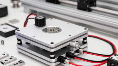
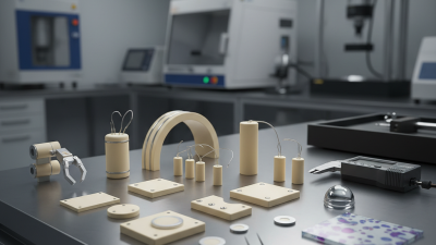
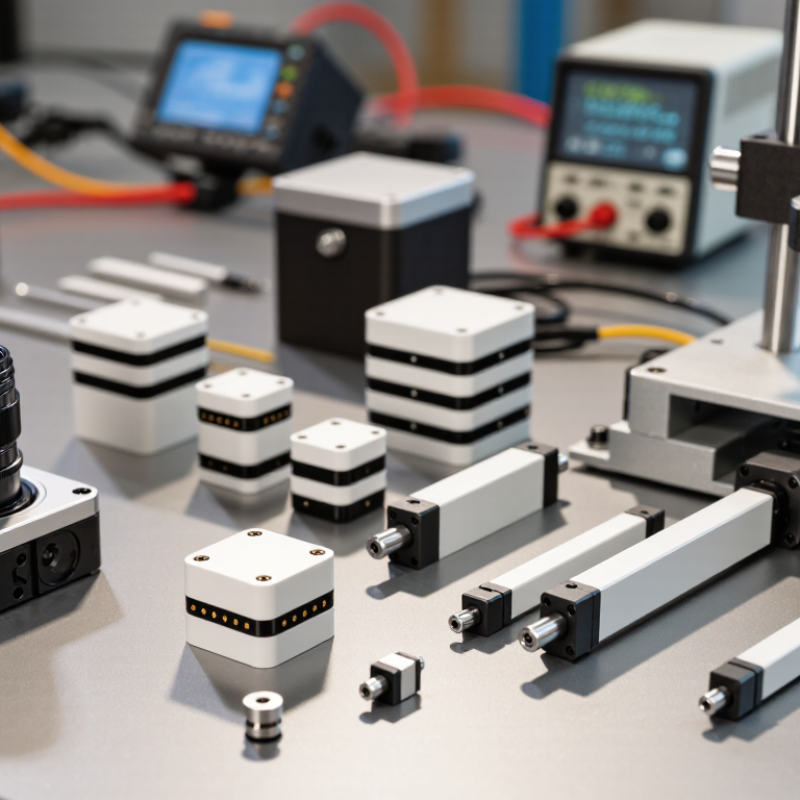
Choosing a piezoceramic actuator starts with the required motion, not the largest advertised stroke. A stack actuator produces direct axial movement with high stiffness and force, making it suitable for fine positioning under load. A bimorph bender moves farther at its tip, but usually provides less force. Flexure-amplified actuators trade some stiffness for greater travel. For motion configuration, choose single-axis travel for simple adjustment, or multi-axis assemblies when alignment requires lateral or tilt correction. Small angular errors matter.
Technical reviews of piezoelectric positioning systems commonly report free strain near 0.1% of actuator length. A 10 mm stack may therefore move roughly 10 μm without amplification; actual travel changes with load, voltage, and preload. Amplified designs can extend travel substantially, but their output force falls. Check the force–displacement curve, not just the maximum stroke. That trade-off is easy to underestimate.
Tips: Sketch the load path and motion direction before comparing models. Allow for thermal drift and hysteresis; closed-loop sensing can improve repeatability. If the actuator will carry a heavy fixture, test it under the real load. Bench results can be a little too optimistic. When space is tight, confirm cable clearance and flexure travel at both endpoints.
Evaluate Stroke, Force, Voltage, and Response Specifications
A piezoceramic actuator’s stroke is usually specified without load. That figure can shrink when the actuator pushes a spring, optic, or moving stage. Compare the required travel under the actual operating load, not just the headline value. Leave margin for assembly tolerances and temperature changes. A neat datasheet number can mislead.
Force ratings need equal care. Check whether the figure describes blocking force, dynamic force, or a recommended working load. These are not interchangeable. A mirror mount may need modest force but precise positioning; a valve mechanism may need greater force and enough travel at the same time. Confirm any preload requirements, since poor support can damage the ceramic. Small details matter.
Voltage and response specifications belong together. The drive voltage determines available stroke, while the driver’s current capability affects how quickly a capacitive actuator can charge. For fast motion, check rise time under the intended electrical load and compare operation with the actuator’s resonant frequency. A quick unloaded test may not reflect a mounted assembly. Piezo systems can also show hysteresis and creep, especially in open-loop positioning. This is easy to underestimate. If repeatability matters, assess sensor feedback and test the complete setup across its working range. A little uncertainty remains until the actuator is mounted.
Check Environmental, Electrical, and Mechanical Compatibility
Choose a piezoceramic actuator for its real surroundings, not just its catalog stroke. Check the full temperature range, including heat from nearby motors or a sunlit enclosure. Ceramic expansion and insulation performance can change with temperature. Check the surroundings. In damp or dusty spaces, ask how the actuator is sealed and whether condensation may form. A thin film of moisture near high-voltage connections is not a minor detail. Keep the mounting surface clean and stable.
Electrical fit matters too. Confirm the maximum drive voltage, waveform, and capacitance; piezo actuators behave mainly as capacitive loads. The driver must supply enough current during fast voltage changes, not merely reach the peak voltage. Then check the stroke under the intended load, along with preload limits and allowable side force. A guide pushing slightly off-axis can reduce motion or damage the ceramic stack. Leave room for wiring and thermal movement. Test the assembly under operating conditions, using a displacement sensor and temperature check where practical. A bench test can mislead. Fixtures sometimes hide small alignment problems.
Validate the Selection Through Testing and Integration
A datasheet can narrow actuator choices, but testing must show how a unit behaves in your actual assembly. Mount it against the intended load, using the same preload and fastening method planned for the machine. Measure displacement with a laser sensor or calibrated gauge while recording voltage, current, and temperature. Small shifts matter. A few micrometres lost to a flexible bracket may undermine precise positioning.
Run repeated cycles at the expected operating rate, then check performance after the actuator warms up. Piezoelectric ceramics can respond differently as temperature, load, and drive conditions change. Watch for hysteresis, creep, settling time, and vibration near resonance. Not always. A clean result on an unloaded bench can be misleading. One test fixture I would question is a rigid block that hides compliance in the real mechanism. Integrate the actuator with its driver, cables, controller, and feedback sensor; confirm that electrical limits and mechanical travel remain within specified ranges. Record failures and adjustments, even when the cause seems obvious. A slightly uneven response may point to mounting stress, but it deserves another measurement before changing the design.
Selection check: This illustrative linear reference is calculated from a nominal free stroke of 10 µm at 100 V. It is not measured product data. Test the candidate actuator under its intended load and drive conditions, then confirm its displacement, hysteresis, and response meet system requirements during integration.