Leave Your Message
  • sns02
  • linkedin (2)
  • sns041
  • whatsapp (2)

2026 Top Piezoceramic Actuator Types How to Choose?

A Piezoceramic Actuator converts an applied voltage into precise mechanical motion. Its travel may be only a few micrometers, yet that movement can position a lens, adjust a valve, or steady a probe. Small movements matter. The right design depends on the job, not just a headline specification.

This 2026 guide introduces common actuator types, including stack, bender, tube, and shear designs. Each has a different balance of stroke, force, speed, and direction of motion. A stacked actuator can produce strong axial force in a compact package, while a bender may offer greater displacement but less force. Tube and shear designs can suit specific positioning or scanning needs. Names and performance figures vary by manufacturer, so compare datasheets under similar conditions.

Selection takes more than matching a force value. Consider the load, required travel, drive voltage, operating frequency, mounting method, and surrounding temperature. Also check hysteresis, creep, insulation, and whether a position sensor or closed-loop controller is needed. Piezo ceramics are stiff and responsive, but they can be damaged by excessive tensile stress or poor installation. A rigid-looking fixture is not automatically a safe one. There are trade-offs. A low-cost option may work, but only after its limits are checked against the real duty cycle. This overview provides a practical basis for comparing actuator types and asking suppliers precise questions before choosing.
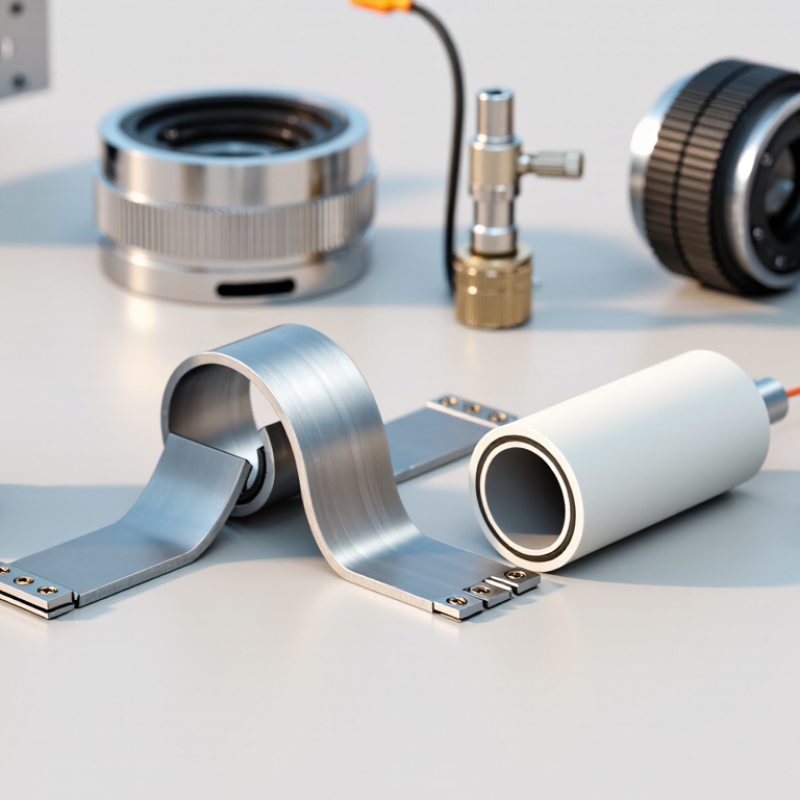
2026 Top Piezoceramic Actuator Types How to Choose?

Piezoceramic Actuator Basics: Structure, Motion, and Operating Principles

A piezoceramic actuator turns an electrical signal into precise mechanical motion. Its core is made from piezoceramic material, often arranged as a stack of thin layers with electrodes between them. Applying voltage creates an electric field across the layers. The ceramic expands or contracts slightly, moving the actuator’s end face. This is the inverse piezoelectric effect.

The movement is tiny. Often, it measures only a few micrometres. Yet the actuator can respond quickly and position a load with fine resolution. A housing and preload mechanism help protect the ceramic from tensile stress; a flexure may guide or amplify its motion. The design matters.

In practice, the stroke depends on voltage, geometry, load, and temperature. Motion is not perfectly proportional to voltage: hysteresis and creep can affect positioning, especially during long holds. A controller with position feedback can improve accuracy, though it adds complexity. When comparing actuator types, check the required travel, force, response speed, and mounting conditions. A small stack may look simple, but its load path is easy to underestimate. The datasheet alone may not reveal every system-level limitation.
Major Piezoceramic Actuator Types and Their Key Differences

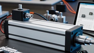
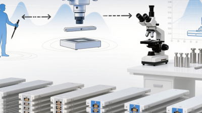
Piezoceramic actuators turn an applied voltage into precise mechanical motion, but their geometry determines how that motion is delivered. Stack actuators expand along one axis, producing high force with relatively short travel. They suit compact positioning stages and valve mechanisms. Small motion matters. A stack also needs careful mounting; uneven clamping can reduce performance or damage the ceramic.

Bender actuators flex like a thin beam. They provide greater displacement at lower force, making them useful for micro-pumps, shutters, and lightweight positioning tasks. Tube actuators can move radially or lengthwise, and are common in scanning mechanisms. Shear actuators shift sideways, offering compact lateral motion for fine alignment. These types are not interchangeable. A bender may travel farther than a stack, yet it cannot usually push the same load.

Choose by comparing required travel, force, response speed, available space, and operating conditions. Check the actuator’s load limits and drive-voltage requirements, then consider hysteresis and temperature effects in the full system. For example, a lens mount may need a short, stiff adjustment, while a small fluid valve may benefit from bending motion. A common mistake is choosing by travel alone. Real assemblies add friction, wiring, and mounting constraints. Test under the actual load; specifications rarely tell the whole story.

Performance Factors: Stroke, Force, Speed, Precision, and Voltage

2026 Top Piezoceramic Actuator Types: How to Choose?

Performance depends on the load, mounting, and drive conditions—not just the actuator type. Industry handbooks commonly give bulk piezoceramic strain near 0.1%, so a 10 mm stack may offer roughly 10 μm of free stroke. Under load, actual travel falls. Check force–displacement curves, not only the advertised maximum force. Uchino’s review in the Journal of Electroceramics (2008) discusses how actuator design shapes practical performance.

Small travel. High force. Fast response.

A stack actuator can move in microseconds, but the controller, wiring, and load may slow the system. For precision, closed-loop sensing helps correct hysteresis and creep; open-loop resolution can look excellent on paper but drift during a long hold. Voltage matters too: compare the rated voltage and required driver, and never assume a higher voltage is safe.

IEC 60483 provides guidance for measuring dynamic properties of piezoelectric ceramics, while published actuator data sheets show that operating ranges vary by construction. A useful selection test is simple: measure stroke and settling time with your real load attached. I would not choose from a catalog number alone.

How to Match an Actuator Type to Your Application Requirements

Matching a piezoceramic actuator starts with the motion your mechanism actually needs. A multilayer stack suits precise axial motion and high blocking force, such as positioning a small optical stage.

Its travel is short: Uchino’s 2008 review in the Journal of Electroceramics describes typical piezoceramic strain around 0.1% of actuator length. A 10 mm stack therefore offers roughly 10 micrometres of free travel, before load and preload reduce it.

Small travel? Measure twice.

For larger movement with lighter loads, a bender can flex several hundred micrometres, but its force and stiffness are lower. Shear actuators provide lateral motion, useful where vertical space is limited; tube actuators can deliver radial or bending motion around a central opening.

These are practical tendencies, not guarantees. Geometry, voltage, temperature, mounting, and load all change performance. Check the supplier’s force–displacement curve and test the actuator in its actual fixture.

A rigid mount can suppress motion; a poor preload can damage a stack. It happens. For an application exposed to vibration, compare resonance and fatigue data, not just nominal displacement.

One uncomfortable point: the “best” type on paper may be wrong after cabling, heat, and assembly tolerances enter the design. Test it.

Integration Considerations: Mounting, Control, Environment, and Testing

When selecting a stack, bender, or tube actuator, match its motion direction and stroke to the load path. Mounting faces should be flat, clean, and stiff; uneven contact can concentrate stress and reduce useful travel. Use the specified preload and keep side loads low, especially for brittle ceramic elements.

Small details matter.

Bonded mounts may simplify assembly, but adhesive thickness and curing variation can change stiffness. Do not assume a rigid-looking bracket is truly rigid.

Control and environment need equal attention. Drive voltage, capacitance, cable length, and amplifier current limits interact, so check actuator data and controller limits together. Use closed-loop sensing when positioning accuracy must hold despite temperature shifts or changing loads. Moisture, dust, and thermal cycling can affect insulation, bonding, and calibration; test suitable protection under actual conditions.

It can drift.

Test the assembled unit, not just the bare actuator: measure displacement, settling time, hysteresis, and temperature rise across repeated cycles. Record the mounting process, waveform, ambient temperature, and load. Some integration assumptions may need revision after the first run.